DSP PAW
source repo: https://code.bitgloo.com/bitgloo/dsp-paw
hackaday: https://hackaday.io/project/190725-dsp-paw
The DSP PAW project provides a complete solution for hands-on teaching of digital signal processing (DSP). It began as my capstone project during university, continued as an undergraduate research project, and has further grown towards a proper end-product.
The highlight of DSP PAW is its ability to provide real-time interactivity. Algorithms written in C++ can be instantly uploaded to and executed from the USB device. Input signals can come from the on-board signal generator, an external source, or from audio files on the host computer. The computer "IDE" can plot the input and output signals, give insights on algorithm performance, modify the sampling configuration, and save sample data to comma-separated files (.csv).
The "USB device" is a NUCLEO-L476RG development board with a custom DSP add-on board:
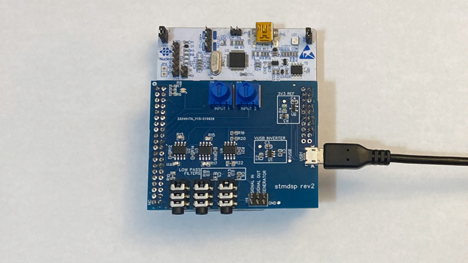
Input and output signals are accessible through either 3.5mm jacks or a 0.1" pin header. The add-on board also provides a status LED and two potentiometers that provide adjustable parameters to algorithms.
Any signals in the +/- 3.3V range can be sampled at rates between 8kS/s and 96kS/s. The number of samples to capture for an algorithm can also be configured by the IDE.
the graphical user interface
The DSP PAW GUI is available for both Windows and Linux-based systems.
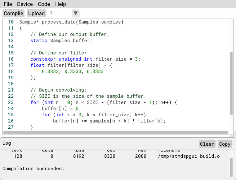
Algorithms are compiled as standalone binaries; they are uploaded to the device's memory, avoiding the need to re-program the micrcontroller. Algorithms are also executed in a fairly sandboxed environment, allowing for hands-free recovery in the case of faulty uploaded code.
example: attenuation
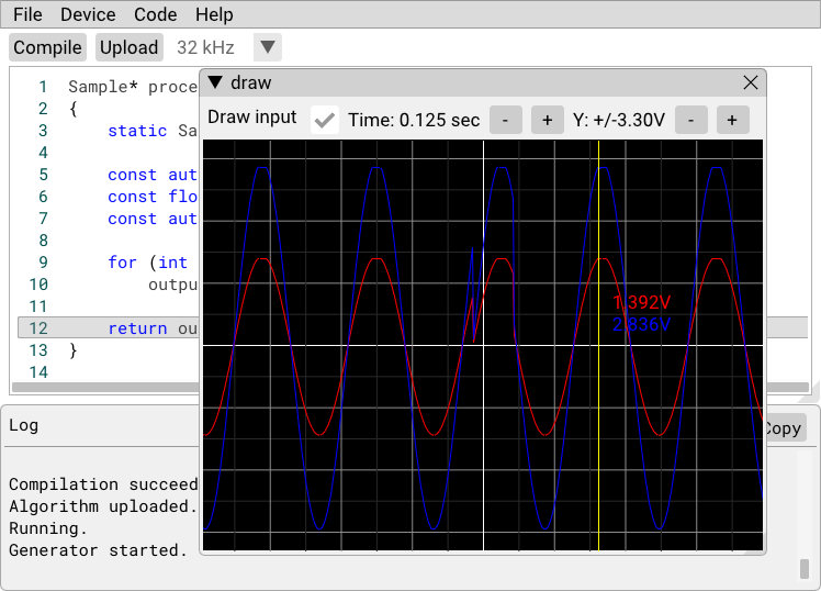
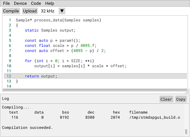
The below algorithm will attenuate the input signal by a factor set with one of the potentiometers:
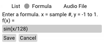
The on-board signal generator is used to create a simple sine wave input:
Finally, the algorithm is executed with the plot view opened to see the results. Adjusting the parameter knob scales the output signal's amplitude. In the below image the scale is set to 0.5; checking the voltage levels of the input (blue) and output (red) signals confirms the algorithm is working as intended.